
Every line of code starts as an idea. Software modeling is how that idea becomes a structured, visual representation before anyone writes a single function or deploys a single build.
Without it, teams guess. Requirements get misread. Architecture decisions happen in someone’s head and never make it to the rest of the group.
This article covers what software modeling is, how it works within the software development lifecycle, the main diagram types including UML structure and behavior models, domain modeling, data modeling, and the tools that teams actually use. You will also learn where modeling helps, where it slows things down, and how it connects to broader practices like model-driven engineering.
What is Software Modeling
Software modeling is the practice of creating abstract representations of a software system using standardized visual notations and diagrams to describe its structure, behavior, and interactions before writing code.
It sits between requirements engineering and actual implementation. You gather what the system needs to do, then you model it.
The Unified Modeling Language (UML) is the most widely adopted notation for this. Standardized by the Object Management Group in 1997, UML gives teams a shared visual vocabulary for describing everything from class hierarchies to user interactions.
But UML is not the only option. Entity-relationship diagrams, flowcharts, BPMN for business processes, and domain-specific modeling languages like SysML all serve different modeling purposes depending on the project context.
Grady Booch, James Rumbaugh, and Ivar Jacobson (known as the “Three Amigos”) merged their competing methods into UML during the mid-1990s at Rational Software. Before that, teams picked between the Booch method, Object Modeling Technique, and Object-Oriented Software Engineering with no common standard.
The core idea is straightforward. You build a blueprint of the system so that developers, architects, and stakeholders can see the same picture before anyone touches a codebase.
Models reduce ambiguity. They catch design flaws early. And they make documenting software far less painful than writing everything from scratch after the fact.
How Does Software Modeling Work
Software modeling works by translating real-world concepts and system requirements into structured visual diagrams that represent objects, their properties, and relationships within a defined context.
The process typically follows three phases rooted in object-oriented analysis and design.
First, you identify the objects. These are real-world things the system interacts with: users, orders, payments, devices, whatever belongs to the problem domain. Each object carries responsibilities and data.
Second, you define relationships. How do these objects connect? A customer places an order. An order contains line items. A payment confirms a transaction. These associations get captured in diagrams like class diagrams or entity-relationship models.
Third, you describe behavior. What happens when a user clicks “checkout”? Sequence diagrams trace the message flow between objects. Activity diagrams map the workflow. State machine diagrams track how an object changes over time.
Most teams start with a design document and then create models that support specific decisions. You model what matters, not everything.
Took me a while to learn that. I’ve seen teams spend weeks modeling every minor class only to throw half of it away when requirements shifted. The practical approach is to model the tricky parts, the areas where miscommunication costs real time.
The software development process determines when modeling happens. In waterfall-style projects, heavy modeling comes upfront. In iterative development, models evolve with the code across multiple cycles.
Tools like Visual Paradigm, Enterprise Architect, StarUML, and even Draw.io handle the actual diagram creation. Some generate source code directly from UML models, though the quality of that generated code varies a lot in practice.
What Are the Types of Software Models
Software models fall into two main categories: structural models that show the static composition of a system, and behavioral models that capture how the system acts over time.
UML 2.5 (the current version, released June 2015) defines 14 diagram types split across these two categories. Not every project uses all of them. Most teams pick three or four that match their specific needs.
Structural diagrams answer “what is the system made of?” Behavioral diagrams answer “what does the system do?”
The software architect usually decides which diagram types a project actually needs based on system complexity and team size.
What Are Structural Software Models
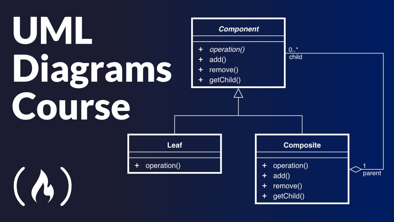
Structural models represent the static parts of a system: classes, components, packages, and how they connect. The class diagram is by far the most common, showing object types, their properties, methods, and relationships like inheritance and composition.
Other structural diagrams include:
- Component diagrams – show how software components are wired together, useful for microservices architecture planning
- Deployment diagrams – map software artifacts to physical or virtual infrastructure like servers and containers
- Package diagrams – organize classes into logical groups, helpful for managing large codebases
- Object diagrams – snapshot of class instances at a specific moment
- Composite structure diagrams – show internal structure and interaction points of a class
What Are Behavioral Software Models
Behavioral models describe the dynamic side: what happens when users interact with the system, how data flows, and how objects change state. Use case diagrams define interactions between external actors and the system.
The key behavioral diagram types:
- Sequence diagrams – trace message exchanges between objects in time order, critical for API integration design
- Activity diagrams – flowcharts for business process workflows and system operations
- State machine diagrams – model how an object transitions between states based on events
- Communication diagrams – show object interactions with emphasis on structural relationships
- Interaction overview diagrams – combine activity and sequence diagram elements
What is Domain Modeling in Software Engineering
Domain modeling is the process of creating a conceptual representation of real-world objects, their properties, and relationships within a specific problem area that the software system addresses.
Eric Evans formalized this approach in his book on Domain-Driven Design (DDD), published in 2003. The idea existed before that, but Evans gave it structure and vocabulary that stuck.
A domain model uses the language of the business, not the language of code. If you are building software for a hospital, your domain model talks about patients, appointments, diagnoses, and prescriptions. Not database tables or API endpoints.
Domain objects fall into three categories in object-oriented analysis:
- Entity objects – core data the system stores and manages (patients, invoices, products)
- Boundary objects – interface points where users or external systems interact
- Control objects – coordinate behavior between entity and boundary objects
The domain model typically gets expressed as a UML class diagram during the feasibility study or early analysis phase. No methods defined at this stage, just concepts, properties, and associations.
Getting domain modeling right matters more than most teams realize. A wrong domain model means your software prototype builds on flawed assumptions. Fixing that later costs significantly more than getting the conceptual foundation right upfront.
The output feeds directly into software requirement specifications and shapes how both functional and non-functional requirements get organized.
What is Data Modeling in Software Development
Data modeling is the process of defining how data is structured, stored, and related within an information system using formal techniques that progress from abstract concepts to physical database implementation.
Peter Chen introduced entity-relationship (ER) notation in 1976 as a semantic modeling technique independent of any specific database technology. That notation is still widely used today.
Data modeling operates at three distinct levels:
- Conceptual data model – high-level view of business data requirements, independent of technology. Identifies the main data subjects and their relationships. Also called the domain model in some contexts.
- Logical data model – adds detail without specifying implementation. Defines tables, columns, data types, and constraints. Serves as the blueprint for application design.
- Physical data model – describes actual database implementation: tablespaces, indexes, partitions, storage allocation, and platform-specific configurations.
The conceptual model gets built first during requirements analysis. Then it refines into a logical model. Finally, the logical model translates into physical database structures using a Data Definition Language.
Tools like Erwin Data Modeler, Enterprise Architect, and ER/Studio handle modeling across all three levels. Most support both relational and dimensional modeling approaches.
Data modeling connects closely to the broader software development lifecycle. Changes to the data model ripple through back-end development, API contracts, and testing strategies.
One thing worth mentioning: data models and information models are not the same thing. An information model is abstract and implementation-independent. A data model is a specific mapping of that information model to a technology, whether that is a relational database, an object model, or an XML schema.
Getting this distinction wrong causes confusion between teams, especially when a software architect and database administrator are working from different definitions.
What is UML in Software Modeling
The Unified Modeling Language is a standardized visual notation for specifying, constructing, and documenting the artifacts of a software system. The Object Management Group adopted it as a standard in 1997, and ISO/IEC published it as ISO/IEC 19505 in 2005.
UML exists because the 1990s had too many competing modeling methods. Grady Booch had his method. James Rumbaugh developed the Object Modeling Technique at General Electric. Ivar Jacobson created Object-Oriented Software Engineering with its use case approach.
Rumbaugh joined Booch at Rational Software in 1994. Jacobson followed in 1995. Together they merged their approaches into what became UML, and a consortium including Microsoft, Oracle, IBM, and HP helped push it toward OMG standardization.
The current version is UML 2.5, released June 2015. It defines 14 diagram types across structural and behavioral categories.
UML is not tied to any programming language. You can model a system in UML and implement it in Java, C++, Python, or anything else. Some tools generate source code directly from UML diagrams, though the practical value of that generated code depends heavily on how detailed your models are.
Worth noting: Microsoft Visual Studio removed UML support in 2016 due to low usage. That says something about how the industry actually uses UML versus how textbooks say it gets used. Most teams pick two or three diagram types rather than using all fourteen.
What Are UML Structure Diagrams
UML structure diagrams represent the static composition of a system. Seven types exist, but class diagrams dominate real-world usage for object-oriented design.
- Class diagrams – object types, properties, methods, inheritance, and associations
- Component diagrams – software component wiring and dependencies
- Deployment diagrams – mapping artifacts to servers, containers, or virtual machines
- Package diagrams – logical groupings of classes and namespaces
- Object diagrams – runtime instance snapshots
- Composite structure diagrams – internal class structure and collaboration points
- Profile diagrams – extend UML for domain-specific use
What Are UML Behavior Diagrams
Behavior diagrams capture the dynamic side, how the system acts, reacts, and changes state over time. Seven types cover different perspectives on system behavior.
- Use case diagrams – actor-system interactions at a high level
- Activity diagrams – workflow and business process flows
- State machine diagrams – object state transitions triggered by events
- Sequence diagrams – time-ordered message exchanges between objects
- Communication diagrams – object interactions emphasizing structural links
- Interaction overview diagrams – combine activity and sequence elements
- Timing diagrams – state changes across a time axis
What is Model-Driven Engineering
Model-Driven Engineering (MDE) is a methodology where models are the primary artifacts driving the entire development process, not just documentation that sits alongside code.
MDE operates through progressive model transformation across three levels:
- Computation-Independent Model (CIM) – describes what the system does from a business perspective, no technology decisions
- Platform-Independent Model (PIM) – defines system logic without binding to any specific platform or language
- Platform-Specific Model (PSM) – maps the PIM to a concrete technology stack
Automated transformations convert each level into the next, eventually generating executable code, technical documentation, configuration files, and test scaffolding.
The Eclipse Modeling Framework is one of the more established open-source platforms for MDE. SysML extends UML specifically for systems engineering contexts where hardware and software interact.
MDE works best for systems with well-defined rules and structures. Financial platforms, embedded systems, telecom infrastructure. It struggles with rapidly changing requirements where the cost of updating models exceeds the cost of just changing code directly.
Honestly, most teams I have worked with land somewhere in the middle. They use models to communicate and document, but they do not rely on automated code generation as the primary development method. The gap between what MDE promises and what it delivers in practice stays wider than the tooling vendors suggest.
What Are Software Modeling Tools
Software modeling tools are applications that let teams create, edit, and manage visual diagrams using standardized notations like UML, BPMN, and entity-relationship models.
The tool you pick depends on team size, budget, and how deeply you commit to model-driven workflows. Here are the main options:
- Lucidchart – web-based, collaborative, supports UML and multiple diagram types. Low learning curve. Good for distributed teams that need real-time editing.
- Visual Paradigm – full UML 2.5 support with code generation, requirements tracing, and database modeling. Desktop and online versions.
- Enterprise Architect by Sparx Systems – heavy-duty modeling for large organizations. Covers UML, SysML, BPMN, ArchiMate, and data modeling. Steep learning curve but extremely capable.
- StarUML – open-source UML tool with a clean interface. Solid for teams that want UML without the enterprise price tag.
- Draw.io (now diagrams.net) – free, web-based, integrates with Google Drive and Confluence. Not UML-specific, but flexible enough for most modeling tasks.
- Erwin Data Modeler – specialized for data modeling using IDEF1X notation. Supports conceptual, logical, and physical data model layers.
Some teams skip dedicated modeling tools entirely and use wireframing tools for UI-level models or plain whiteboards for architecture sketches. At least in my experience, the best tool is the one your team actually uses consistently.
A web development IDE like VS Code can also handle lightweight modeling through extensions, though it lacks the full diagramming features of purpose-built tools.
What is the Difference Between Software Modeling and Software Design
Software modeling creates abstract visual representations of a system. Software design makes concrete implementation decisions about how that system gets built. They overlap, but they are not the same activity.
Modeling focuses on “what” and “how things relate.” Design focuses on “how to build it.” A class diagram models the relationships between objects. A design decision picks which design pattern like dependency injection to apply for those objects.
In the software development lifecycle, modeling typically starts during requirements analysis and continues through high-level design. Detailed design decisions happen later, closer to implementation.
The line between software development and software engineering matters here too. Engineering emphasizes systematic modeling and documentation. Development often leans toward faster, lighter approaches where modeling is minimal.
A useful way to think about it: all software design involves some modeling (even mental models count), but not all modeling results in design decisions. You can model a system purely for documentation or communication without making any design choices at all.
What Are the Benefits of Software Modeling

Software modeling reduces miscommunication between developers, project roles, and business stakeholders by providing a shared visual language that does not require reading code.
Concrete benefits:
- Earlier defect detection – structural and logical flaws surface during modeling instead of during testing or production
- Clearer requirements – models force precision that written specs alone cannot achieve, reducing gaps in the requirement specification
- Faster onboarding – new team members understand system architecture from diagrams instead of reading thousands of lines of code
- Better maintainability – documented models make post-deployment maintenance and code refactoring less risky
- Cross-team alignment – front-end and back-end teams, QA, and product owners all reference the same diagrams
Models also serve as living documentation when maintained alongside the code. They complement a software development plan by visualizing the architecture that the plan describes in text.
The quality assurance process benefits too. QA engineers use behavioral models like activity and sequence diagrams to derive test cases and verify that the system behaves according to the modeled interactions.
What Are the Limitations of Software Modeling
Software modeling adds overhead. Every hour spent diagramming is an hour not spent writing code, and the return on that investment varies dramatically by project type and team maturity.
Known limitations:
- Model decay – models that are not updated alongside code become misleading documentation, worse than no documentation at all
- UML complexity – 14 diagram types with extensive notation rules create a steep learning curve that discourages adoption across teams
- Over-modeling risk – teams can waste weeks modeling every class and interaction when only critical areas justified the effort
- Tool fragmentation – models built in one tool rarely transfer cleanly to another despite XMI interchange standards
- False precision – detailed models can create a false sense of completeness when requirements are actually still ambiguous
Microsoft Visual Studio dropped UML support in 2016. That was a signal that heavy UML adoption did not match how most software development teams actually work.
Agile and lean software development teams tend to prefer lightweight modeling, whiteboards, quick sketches, and just enough documentation to communicate intent. The best practice is to model the complex parts and skip the obvious ones.
Projects that follow rapid development cycles often find formal modeling too slow for their pace. The models become outdated before the next sprint finishes.
Still, dismissing modeling entirely is a mistake for complex systems. The trick is calibrating how much modeling a specific project actually needs, and being honest when that answer is “not much.”
FAQ on What Is Software Modeling
What is the main purpose of software modeling?
Software modeling creates abstract visual representations of a system’s structure and behavior. It helps developers, architects, and stakeholders understand how components connect and interact before writing code, reducing miscommunication and catching design flaws early in the development process.
What is the difference between UML and software modeling?
UML is one specific notation used for software modeling, standardized by the Object Management Group in 1997. Software modeling is the broader practice that includes UML, entity-relationship diagrams, BPMN, SysML, and other visual methods for representing system designs.
What are the two main categories of software models?
Structural models show the static composition of a system, things like classes, components, and deployment nodes. Behavioral models capture dynamic aspects, including user interactions, state transitions, message flows, and activity workflows over time.
Who created UML?
Grady Booch, James Rumbaugh, and Ivar Jacobson created UML at Rational Software in the mid-1990s by merging the Booch method, Object Modeling Technique, and Object-Oriented Software Engineering. The Object Management Group adopted it as a standard in 1997.
What is domain modeling in software engineering?
Domain modeling is a conceptual representation of real-world objects, their properties, and relationships within a specific problem area. Eric Evans formalized this approach through Domain-Driven Design. It uses business language rather than technical terminology to describe system concepts.
What tools are used for software modeling?
Common tools include Lucidchart, Visual Paradigm, Enterprise Architect, StarUML, Draw.io, and Erwin Data Modeler. Selection depends on team size, budget, and modeling depth. Some teams use wireframing tools or whiteboard sketches for lightweight modeling.
Is software modeling necessary for agile projects?
Agile teams typically use lightweight modeling rather than heavy upfront documentation. Quick whiteboard sketches and focused diagrams for complex areas replace comprehensive UML packages. The principle is to model just enough to communicate intent without slowing incremental development cycles.
What is model-driven engineering?
Model-Driven Engineering treats models as primary development artifacts rather than documentation. It transforms computation-independent models into platform-specific models through automated processes, eventually generating executable code, configurations, and test scaffolding from the models directly.
How does data modeling differ from software modeling?
Data modeling specifically addresses how data is structured, stored, and related across conceptual, logical, and physical levels. Software modeling covers the entire system, including behavior, user interactions, component architecture, and deployment. Data modeling is one subset of the broader practice.
Can software models generate actual code?
Some tools like Visual Paradigm and Enterprise Architect generate source code from UML diagrams. The practical quality depends on model detail and complexity. Most teams use generated code as a starting skeleton rather than production-ready output, then refine it through standard code review processes.
Conclusion
Understanding what is software modeling comes down to one thing: making the invisible visible before committing to code. Whether you use UML class diagrams, entity-relationship models, or lightweight whiteboard sketches, the goal stays the same.
The right level of modeling depends on your project. Complex systems with multiple teams and strict compliance requirements benefit from formal structural and behavioral diagrams. Smaller projects running feature-driven development cycles get by with focused domain models and quick sequence diagrams.
Tools like Visual Paradigm, Enterprise Architect, and StarUML make the process manageable. But no tool fixes a poorly understood problem domain.
Model what is hard to communicate. Skip what is obvious. Keep models updated or delete them. Outdated diagrams are worse than no diagrams at all.
Software modeling is not about perfection. It is about clarity, alignment, and building a shared understanding that carries through from requirements all the way to deployment.
- Google Play Store Not Working: How to Fix It - July 22, 2026
- How to Make a Repository Private in GitHub - July 20, 2026
- How to Set Up Google Play Family Library - July 18, 2026


